Voltage Transformer Test Set
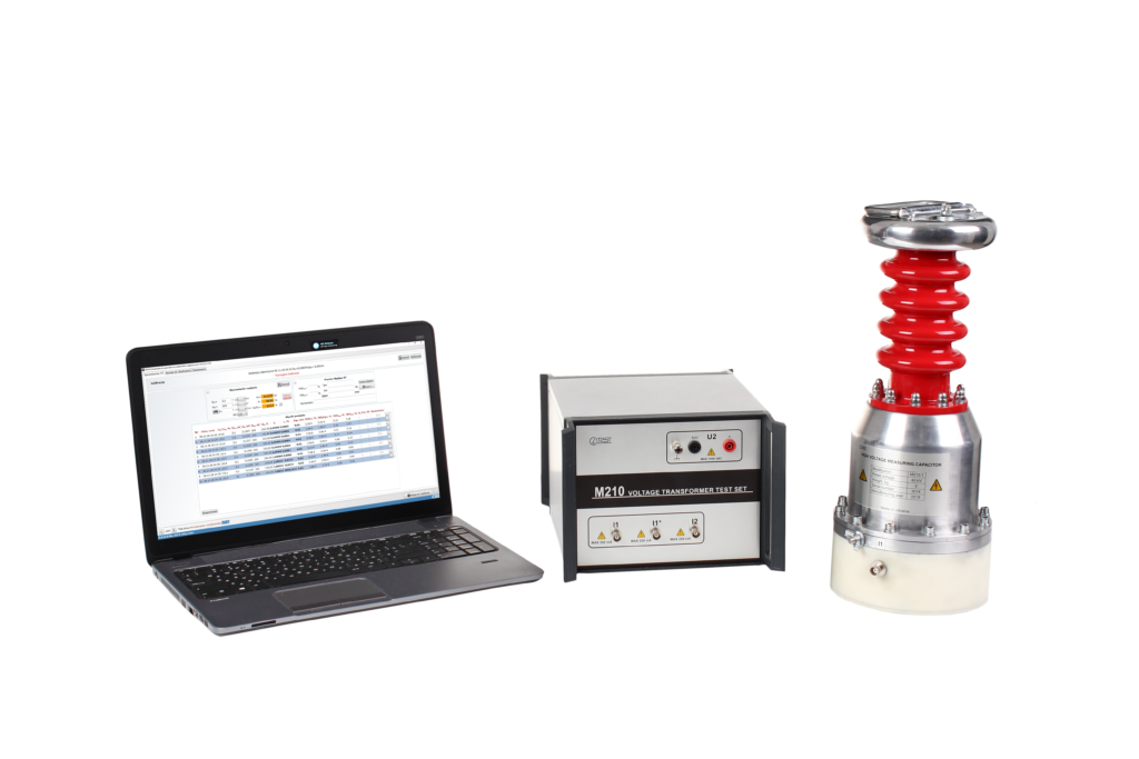
Voltage Transformer Test Set M210/M211 measures voltage transformer (VT) errors with the method based on high voltage capacitance bridge. This method provides accurate measurement of the VT errors in continuous ranges of primary and secondary voltages. The method allows to decrease dimensions and weight of the equipment significantly
M210/M211 can also be used as a capacitive high-voltage bridge for measuring capacitance and dissipation factor (tanδ) during testing of high voltage equipment *
* Additional function. Can be supplied upon customer’s request
FEATURES AND BENEFITS
- Measurement of VT errors in continuous ranges of primary and secondary voltages
- High measurement accuracy (VT testing): up to ± 0,005 % and ± 0,3 min
- High measurement accuracy (С&tanδ testing): up to ± 0,005 % (Cx) and ± 0,00005 (tanδ)
- Measurement of true RMS values of primary and secondary voltages, THD and n-th harmonic ratios (up to 40-th) measurement
- A more cost-effective solution than combination of standard voltage transformers or voltage divider and comparator
- Easy handling
- Small size and low weight
APPLICATIONS
M210/M211 is used by:
- Manufacturers of Voltage Transformers
- On-site Voltage Transformer testing
- Calibration Laboratories
- Metrology Institutes
* Additional function. Can be supplied upon customer’s request
VERSIONS
Voltage Transformer Test Set M210/M211 is available in six versions, which differ in accuracy class and maximum primary voltage. More details of the M210/M211 versions are given in the tables of technical ranges of primary and secondary voltages
| M210/M211 version | Primary voltage range (U1), kV | Secondary voltage range (U2), V | Rated voltage of High Voltage Capacitors (UCH), kV |
| M210.1 | 0,01…45 | 0,6…1000 | 45 |
| M211.1 | |||
| M210.2 | 0,01…100 | 100 | |
| M211.2 | |||
| M210.3 | 0,01…230 | 230 | |
| M211.3 |
TEST ARRANGEMENT
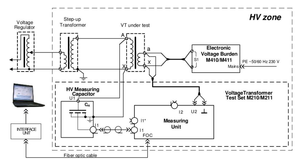
Fig.1 VT testing
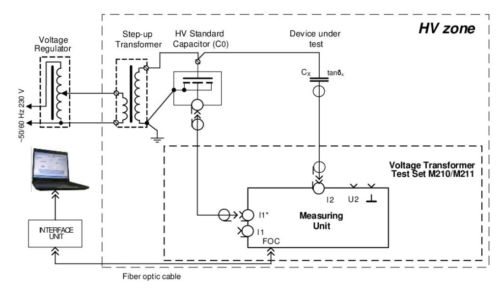
Fig. 2 С&tanδ testing*
Measurement ranges and error limits of VT Test Set M210 – VT testing
|
Name |
Measurement range | Limits of absolute measurement error |
Additional conditions |
|
| Ratio error, ε | – 100 % ≤ ε ≤ 100 % | ± 0,015 % | |Δφ| ≤ 100 min
|
300 V ≤ U1 ≤ UСH,
6 V ≤ U2 ≤ 1000 V |
| ± 0,05 % | |Δφ| ≤ 100 min
|
100 V ≤ U1 < 300 V,
6 V ≤ U2 ≤ 1000 V |
||
| ± 0,1 % | |Δφ| > 100 min | 100 V ≤ U1≤ UСH,
6 V ≤ U2 ≤ 1000 V |
||
| ± 0,5 % | 10 V ≤ U1 < 100 V and/or 0,6 V≤ U2< 6 V | |||
| Phase displacement, Δφ | – 300 min ≤ Δφ ≤ 300 min | ± 1 min | |Δφ| ≤ 100 min | 300 V ≤ U1 ≤ UСH,
6 V ≤ U2 ≤ 1000 V |
| ± 3 min | |Δφ| ≤ 100 min | 100 V ≤ U1 < 300 V,
6 V ≤ U2 ≤ 1000 V |
||
| ± 5 min | |Δφ| > 100 min
|
100 V ≤ U1 ≤ UСH,
6 V ≤ U2 ≤ 1000 V |
||
| ± 10 min | 10 V ≤ U1< 100 V and/or 0,6 V ≤ U2< 6 V | |||
| Relative value of secondary voltage, US/ USr | 2…190 % | ± 1 %* | 0,6 V ≤ U2≤ 1000 V | |
| Test voltage frequency, f | 49…51 Hz** | ± 0,02 Hz | – | |
Measurement ranges and error limits of VT Test Set M211 – VT testing
|
Name |
Measurement range | Limits of absolute measurement error |
Additional conditions |
|
| Ratio error, ε | – 100 % ≤ ε ≤ 100 % | ± 0,005 % | |Δφ| ≤ 30 min | 300 V ≤ U1 ≤ UСH
6 V ≤ U2 ≤ 1000 V |
| ± 0,01 %
|
30 min< |Δφ| ≤100 min | |||
| ± 0,05 % | |Δφ| ≤ 100 min | 100 V ≤ U1 < 300 V,
6 V ≤ U2 ≤ 1000 V |
||
| ± 0,1 % | |Δφ| > 100 min | |||
| ± 0,5 % | 10 V ≤ U1< 100 V and/or 0,6 V≤ U2< 6 V | |||
| Phase displacement, Δφ | – 300 min ≤ Δφ ≤ 300 min | ± 0,3 min | |Δφ| ≤ 30 min | 300 V ≤ U1 ≤ UСH,
6 V ≤ U2 ≤ 1000 V |
| ± 1 min | 30 min< |Δφ| ≤100 min | |||
| ± 3 min | |Δφ| ≤ 100 min | 100 V ≤ U1 ≤ 300 V,
6 V ≤ U2 ≤ 1000 V |
||
| ± 5 min | |Δφ| > 100 min | 100 V ≤ U1 ≤ UСH
6 V ≤ U2 ≤ 1000 V |
||
| ± 10 min | 10 V ≤ U1< 100 V and/or 0,6 V ≤ U2 < 6 V | |||
| Relative value of secondary voltage, US/ USr | 2…190 % | ± 1 %* | 0,6 V ≤ U2≤ 1000 V | |
| Test voltage frequency, f | 49…51 Hz** | ± 0,02 Hz | – | |
Measurement ranges and absolute error limits of VT Test Set M210 – С&tanδ testing
| СХ/С0 |
Limits of relative measurement error of δC, % |
Limits of absolute measurement error of dissipation factor Δtanδ |
Test current , А |
| 0,01…0,1 |
±[1×10⁻² +2×10⁻⁴×(C0/CX -10) +|tanδX – tanδ0|] |
±[1×10⁻⁴ + 2×10⁻⁶×(C0/CX -10) +0,005×| tanδX – tanδ0|] |
up to 0,2 |
| 0,1…103 | ±[1×10⁻² + |tanδX – tanδ0|] | ±[1×10⁻⁴ + 0,005×|tanδX – tanδ0|] |
Measurement ranges and error limits of VT Test Set M211 – С&tanδ testing
| СХ/С0 |
Limits of relative measurement error of δC, % |
Limits of absolute measurement error of dissipation factor Δtanδ |
Test current , А |
| 0,01…0,1 |
±[5×10⁻³ +2×10⁻⁴×(C0/CX – 10) +|tanδX – tanδ0|] |
±[5×10⁻⁵ + 2×10⁻⁶×(C0/CX – 10) +0,005×| tanδX – tanδ0|] |
up to 0,2 |
| 0,1…103 | ±[5×10⁻³ + |tanδX – tanδ0|] | ±[5×10⁻⁵ + 0,005×|tanδX – tanδ0|] |
Measurement ranges and error limits of VT Test Set M210/M211 – voltage parameters testing
| Name | Range | Error limits | Additional conditions | |
| True RMS voltage, V | U1 | 300…UСH | dU = ±0,5 % | Сн using |
| U2 | 10…1000 | – | ||
|
First harmonic true RMS voltage, V |
U11 | 300…UСH | dU = ±0,5 % | Сн using |
| U21 | 10…1000 | – | ||
| Primary voltage THD (KU1), % | 0…20 | ΔKu1 = ±0,2 % | Сн using at KU1<2 | |
| dKu1 =±10 % | Сн using at KU1≥2 | |||
| Secondary voltage THD (KU2), % | 0…20 | ΔKu2 = ±0,2 % | at KU2<2 | |
| dKu2 =±10 % | at KU2≥2 | |||
| Primary voltage nth harmonic ratio (KU1(n)), % | 0…15 | ΔKu1(n) = ±0,05 % | Сн using at KU1(n)<1 | |
| dKu1(n) =±5 % | Сн using at KU1(n)≥1 | |||
| Secondary voltage nth harmonic ratio (KU2(n)), % | 0…15 | ΔKu2(n) = ±0,05 % | at KU2(n)<1 | |
| dKu2(n) =±5 % | at KU2(n)≥1 | |||
| Frequency (f), Hz | 49…51 | ±0,02 | – | |
| Power mains: | |||||||||
| Measuring unit | built-in rechargeable battery | ||||||||
| Charging and Calibration power supply unit | 220/230 V, 50 Hz | ||||||||
| Operating Temperature | -10 … 40 °С | ||||||||
| Relative Humidity | up to 80% non-condensing | ||||||||
| Size, mm | Measuring unit |
HV capacitor |
|||||||
|
45 kV |
100 kV |
230 kV |
|||||||
|
250 x 350 x 185 |
170 x 425 |
260 x 610 |
390 x 995 |
||||||
| Weight, kg |
10 |
7 |
17 |
55 |
|||||
| Standards
Safety EMC |
EN 61010-1:2010 EN 61326-1:2013 |
||||||||
| Calibration interval | 3 years recommended | ||||||||