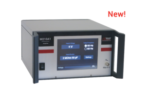
Amplifier
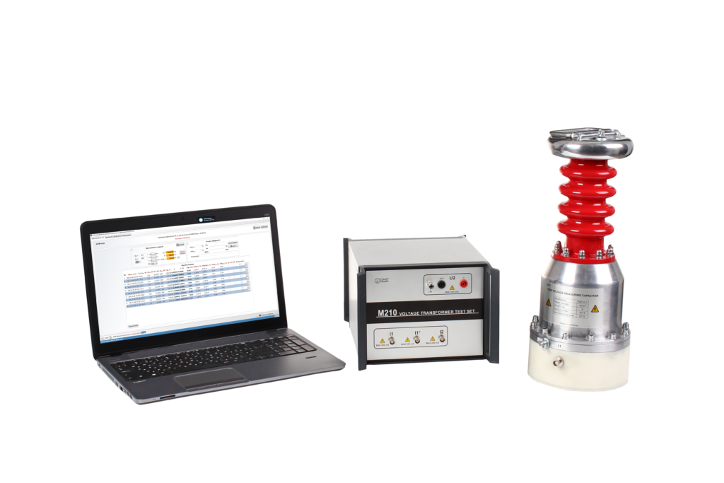
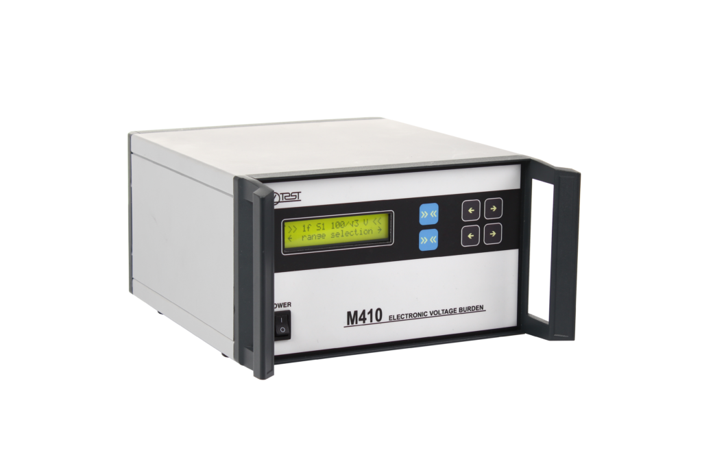
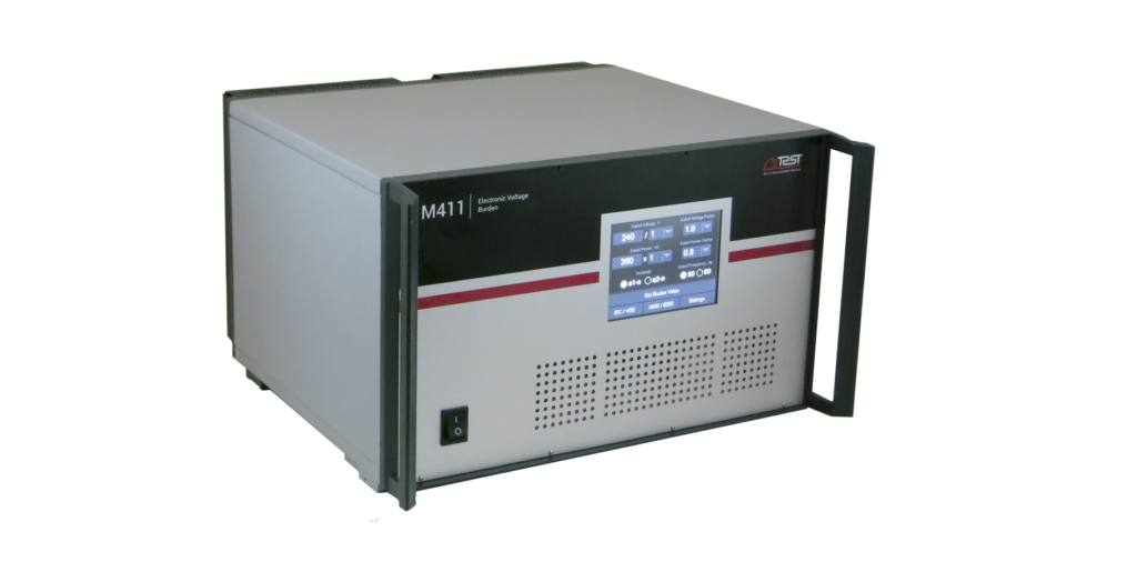
The M210А1 Amplifier provides:
- verification and calibration of low-power voltage transformers (LPVT) as part of any VT calibration system;
- conversion of any secondary voltage of a traditional VT into a value equal to the nominal voltage of the reference VT.
FEATURES AND BENEFITS
- Continuous range of rated secondary voltages of verified LPVT
- Continuous range of rated secondary voltages of verified traditional VT
- High conversion accuracy
- Simple use by intuitive user interface
- Storage of individual voltage settings
- Possibility of using with automated VT calibration system
APPLICATIONS
M210A1 is used by:
- Manufacturers of LPVT and VT
- Calibration Laboratories
- Metrology Institutes
| Input 1: | |
| Rated input voltage range (Uin1r) | 0,1 V … 4 V |
| Input voltage resolution | 0,001 V |
| Additional factors | × 1/√3; × 1/3 |
| Rated operating frequency | 50/60 Hz |
| Input impedance, represented as a parallel resistor-capacitor circuit | 2 МΩ ±5% || C ≤ 50 pF |
| Input 2: | |
| Rated input voltage range (Uin2r) | 30 V … 245 V |
| Input voltage resolution | 0,1 V |
| Additional factors | × 1/√3; × 1/3 |
| Rated operating frequency | 50/60 Hz |
| Input impedance, represented as a parallel resistor-capacitor circuit | 2 МΩ ± 5% || C ≤ 50 pF |
| Output: | |
| Rated output voltage range (Uoutr) | 30 V … 100 V |
| Output voltage range | 0 … 120 V |
| Output voltage resolution | 0,1 V |
| Additional factors | × 1/√3; × 1/3 |
| External burden | R ≥ 500 kΩ; C ≤ 5 nF |
| Accuracy: | |
| Ratio error (Uoutr/Uinr) 0,02·Uoutr ≤ Uout < 0,2·Uoutr 0,2·Uoutr ≤ Uout < 0,8·Uoutr 0,8·Uoutr ≤ Uout < 1,9·Uoutr | ± 0,1 % ± 0,04 % ± 0,02 % |
| Phase displacement 0,02·Uoutr ≤ Uout < 0,2·Uoutr 0,2·Uoutr ≤ Uout < 0,8·Uoutr 0,8·Uoutr ≤ Uout < 1,9·Uoutr | ± 5 min (± 0,15 crad) ± 2 min (± 0,06 crad) ± 1 min (± 0,03 crad) |
| Power mains: Voltage Rated frequency | 100…240 V 50/60 Hz |
| Operating temperature Relative humidity | 0...40 °C up to 80 % non-condensing |
| Size Weight | 245 × 135 × 325 mm 5 kg |
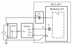
CL – low-voltage measuring capacitor; CH – high-voltage measuring capacitor;
CC – current comparator with automatic balancing.
Fig.1 Test circuit for LPVT by use the Voltage Transformer Test Set M210/M211
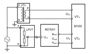
VTN – standard transformer
Fig.2 Test circuit for LPVT by use the Comparator M100
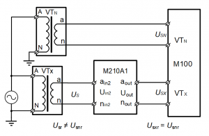
VTN – standard transformer; VTX– transformer under calibration
Fig.3 Test circuit for traditional voltage transformers with different rated secondary voltages


