

Precision High Voltage Capacitance Bridge
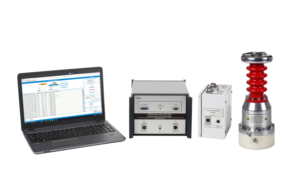
Precision High Voltage Capacitance Bridge M201 measures the capacitance and dissipation factor (tanδ) with high accuracy
Measuring using M201 requires the use of the external high voltage standard capacitor
Maximum test voltage is limited higest voltage value of standard capacitor
FEATURES AND BENEFITS
- High measurement accuracy C&tanδ testing: up to ± 0,002 % (Cx) and ± 0,00002 (tanδ)
- Measurement of C&tanδ at test current up to 50 A
- Easy handling
- Small size and low weight
APPLICATIONS
M201 is used for:
- Precision C&tanδ measurement of standard capacitors
- Precision C&tanδ measurement of capacitors and HV cables with large capacitance
- C&tanδ testing on rated voltage of: Instrument Transformers, Power Transformers, Bushings, Switches, Surge Arresters, Capacitors, Cables
- Metrological research
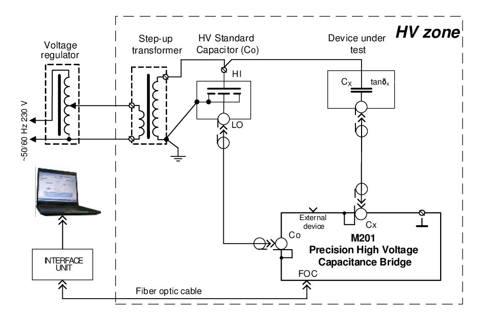
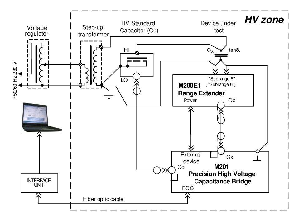
TEST ARRANGEMENT
The circuit for measurements of capacitance less than 1 μF (test current up to 0,5 A)
The circuit for measurements of capacitance more than 1 μF (test current up to 50 A)
Measurement ranges and error limits of M201 without error limits of the standard capacitor
|
# subr |
СХ/С0 | Allowable current flowing through the measurement object circuit , А | Limits of relative error for the capacitance measurement, % |
Limits of absolute error for the dissipation factor measurement |
| 1 | 0,01…0,1 | 0…0,5 | ±[2×10⁻³ +2×10⁻⁴×(C0/CX -10) +|tanδX – tanδ0|] |
±[2×10⁻⁵ + 2×10⁻⁶×(C0/CX -10) + 0,005×|tanδX – tanδ0|] |
| 0,1…1,0 | ±[1×10⁻³ + |tanδX – tanδ0|] | ±[1×10⁻⁵ + 0,005×|tanδX – tanδ0|] | ||
| 2 | 1,0…10 | |||
| 3 | 10…102 | |||
| 4 | 102…103 | ±[2×10⁻³ + |tanδX – tanδ0|] | ±[2×10⁻⁵ + 0,005×|tanδX – tanδ0|] | |
| 5* | 103…104 | 0,03…5 | ±[5×10⁻³ + |tanδX – tanδ0|] | ±[5×10⁻⁵ + 0,005×|tanδX – tanδ0|] |
| 6* | 104…105 | 0,3…50 |
* – with M200E1 using
Measurement ranges and error limits of M201 with the standard capacitor using. Capacitor is the part of M201
|
# subr |
СХ/С0 | Allowable current flowing through the measurement object circuit , А | Limits of relative error for the capacitance measurement, % |
Limits of absolute error for the dissipation factor measurement |
| 1 | 0,01…0,1 | 0…0,5 | ±[5×10⁻³ +2×10⁻⁴×(C0/CX -10) +|tanδX – tanδ0|] |
±[5×10⁻⁵ + 2×10⁻⁶×(C0/CX -10) + 0,005×|tanδX – tanδ0|] |
| 0,1…1,0 | ±[4×10⁻³ + |tanδX – tanδ0|] | ±[4×10⁻⁵ + 0,005×|tanδX – tanδ0|] | ||
| 2 | 1,0…10 | |||
| 3 | 10…102 | |||
| 4 | 102…103 | ±[5×10⁻³ + |tanδX – tanδ0|] | ±[5×10⁻⁵ + 0,005×|tanδX – tanδ0|] | |
| 5* | 103…104 | 0,03…5 | ±[8×10⁻³ + |tanδX – tanδ0|] | ±[8×10⁻⁵ + 0,005×|tanδX – tanδ0|] |
| 6* | 104…105 | 0,3…50 |
* – with M200E1 using
| Limits of relative error for the testing voltage measuremen | ±1 % |
| Limits of absolute error for the testing voltage frequency measurement | ±0,1 Hz |
| Power mains: | |
| Measuring unit | built-in rechargeable battery |
| Charging unit: | |
| Rated Voltage | 220/230 V |
| Rated Frequency | 50 Hz |
| Normal conditions: | |
| Temperature range | 15°С … 25°С |
| Relative Humidity | Up to 80 %. non-condensing |
| Operating Temperature | 0 … 40 °С |
| Relative Humidity | Up to 80 % non-condensing |
| Size: | |
| M201 | 250 x 185 x 350 mm |
| M200E1 | 130 x 200 x 200 mm |
| Weight: | |
| M201 | 10 kg |
| M200E1 | 4 kg |
| Standards compliance:
Safety EMC Calibration Interval |
IEC 61010-1:2010 IEC 61326-1:2013 2 years recommended |
* – measuring at the frequency of 60 Hz can be agreed with the customer